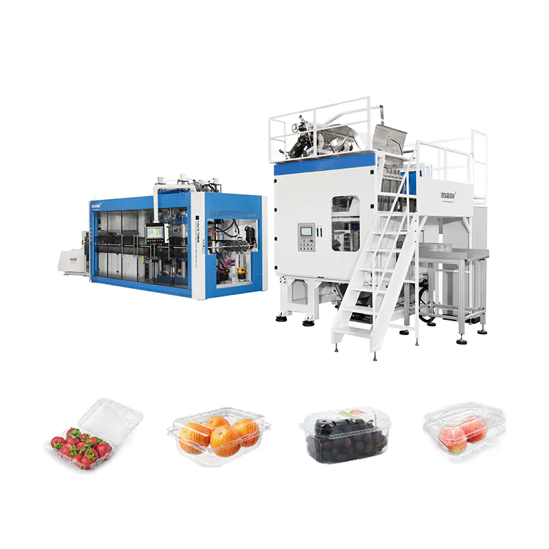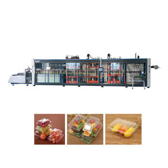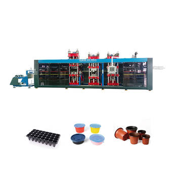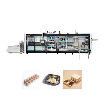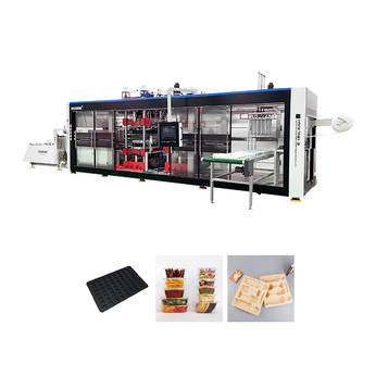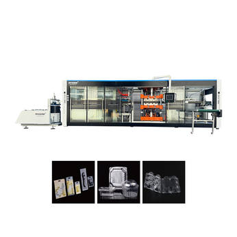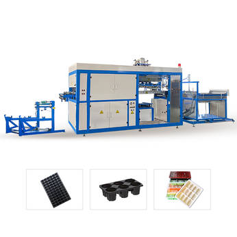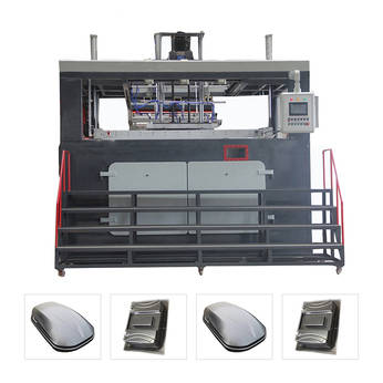
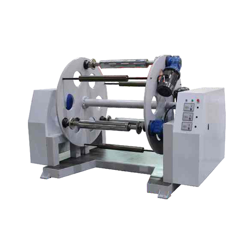
A production line built around a thermoforming machine is only as reliable as the tooling and support equipment feeding it. Mould wear, inconsistent sheet handling, and neglected regrind systems rarely fail all at once. Instead, they degrade output quality in small increments: a slightly deeper vent mark here, a webbing defect there, until scrap rates climb without an obvious single cause.
Plant engineers who track downtime causes consistently find that unplanned mould repairs and auxiliary equipment breakdowns account for a disproportionate share of lost production hours compared to core machine failures. This is not because tooling is inherently fragile, but because it receives the least scheduled attention relative to how much cyclical stress it absorbs. Each forming cycle exposes the mould surface to rapid heating, mechanical clamping force, and vacuum draw, all of which compound over tens of thousands of cycles.
The sections below break down practical, technically grounded maintenance practices across three interconnected areas: the mould and tooling itself, the auxiliary systems that support forming, and the extruder-side equipment that prepares and recycles material. The goal is a maintenance rhythm that catches wear before it becomes a defect, and catches equipment drift before it becomes downtime.
Understanding how a mould actually fails is the starting point for any maintenance plan. Three wear mechanisms dominate in production environments, and each leaves a distinct signature that trained operators can learn to spot early.
Repeated contact with heated sheet, especially filled or reinforced polymer grades, gradually dulls the mould surface finish. A cavity that once released parts cleanly begins to show drag marks, and gloss-critical parts start showing inconsistent sheen across a single run.
Vent holes are small by design, typically under a millimeter in diameter, which makes them the first feature to clog with resin dust, release agent residue, or condensed moisture. Clogged vents show up as trapped-air bubbles or incomplete detail replication in corners, while over time the constant vacuum draw can also erode the vent edges, widening them beyond tolerance.
Aluminum tooling, the most common mould material for thermoforming, expands and contracts with every cycle. Over extended production runs this creates micro-cracking, most often at thin ribs, sharp internal corners, or areas near cooling channels where thermal gradients are steepest. Left unchecked, hairline cracks propagate and eventually require a full insert replacement rather than a simple weld repair.
| Wear Type | Primary Cause | Recommended Inspection Interval |
|---|---|---|
| Surface abrasion | Abrasive fillers, repeated sheet contact | Every 15,000 to 20,000 cycles |
| Vent clogging | Resin dust, release agent buildup | Weekly visual check, monthly deep clean |
| Thermal fatigue cracking | Cyclical heating and clamping stress | Quarterly dye-penetrant or visual inspection |
| Cooling channel scaling | Hard water mineral deposits | Every 3 to 6 months depending on water quality |
Maintenance plans fail more often from poor scheduling design than from lack of technical knowledge. A schedule that demands too much of operators on a busy shift gets skipped; a schedule that is too vague gets interpreted inconsistently. The table below outlines a tiered structure that separates fast checks operators can do between cycles from deeper work reserved for scheduled downtime.
| Frequency | Task | Typical Duration |
|---|---|---|
| Every shift | Visual check of part release, surface marks, and trim edges | 5 minutes |
| Daily | Wipe down mould surface, check release agent application | 10 to 15 minutes |
| Weekly | Clear vent holes, inspect clamp frame alignment | 30 to 45 minutes |
| Monthly | Deep clean cooling channels, check heater element output | 1 to 2 hours |
| Quarterly | Full dimensional check against master tooling record | Half shift |
One practical detail that improves compliance: pair each task with a physical location, such as a laminated card near the tooling storage rack, rather than relying only on a digital work order that operators have to remember to check. Plants that log completion directly on the mould cart consistently show fewer skipped intervals than those relying purely on centralized software reminders.
Beyond the mould itself, a properly maintained thermoforming auxiliary equipment setup, covering sheet feeding, trimming, stacking, and edge handling, has a direct effect on how much stress the tooling absorbs. Poorly tensioned sheet feed rollers, for instance, cause uneven material draw into the mould cavity, which forces the tooling to compensate through deeper vacuum draw or longer heating dwell, both of which accelerate wear.
Feed roller alignment should be checked whenever sheet width or gauge changes. Misalignment as small as a few millimeters across a wide sheet can create tracking drift that shows up as inconsistent wall thickness on one side of the formed part.
Dull trim blades do not just produce ragged edges; the added cutting resistance transmits vibration back through the line, which over time loosens fasteners on adjacent stations, including the mould clamp frame. A blade sharpness check belongs on the same interval as the mould vent inspection, since both directly affect part edge quality.
In auxiliary staging areas, uncontrolled humidity encourages material absorption in hygroscopic resins, which then causes surface blemishes during forming that are easy to misattribute to the mould rather than the upstream sheet condition. A simple humidity log at the staging rack helps separate tooling issues from material conditioning issues during troubleshooting.
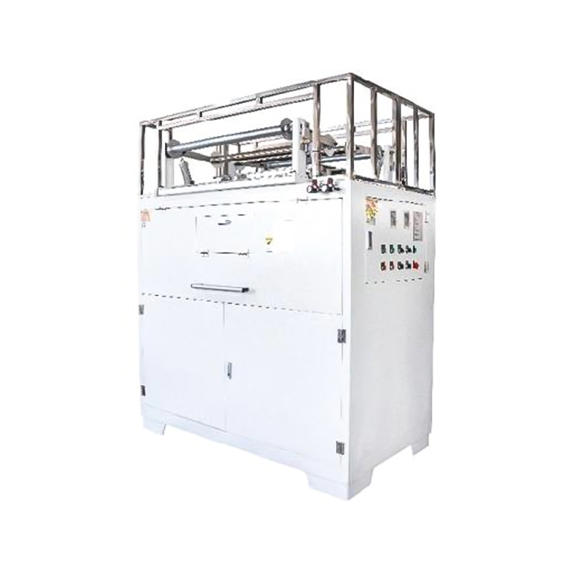
For lines that run in-house sheet extrusion ahead of forming, the extruder auxiliary machine/crusher stage determines regrind quality, and regrind quality feeds directly back into how consistently the mould performs. Contaminated or inconsistently sized regrind creates localized thin spots and gel defects that no amount of mould adjustment can fully correct.
Dull crusher blades produce irregular regrind particle size, mixing fine dust with oversized flakes in the same batch. This uneven particle distribution feeds unevenly into the extruder hopper, creating localized melt inconsistency downstream. Screens should be inspected for tearing or enlarged mesh openings on a fixed interval rather than only when output visibly degrades.
Screen changers on the extruder side accumulate gels and carbonized resin over time. A pressure rise across the screen pack is the clearest early indicator that a change is due; waiting for a full blockage risks a pressure spike that can damage the die or the drive train.
Running too high a proportion of regrind relative to virgin material tends to concentrate contamination and degrade melt strength over successive cycles. Most processors find a stable operating point somewhere between a fifth and a third regrind content, though the right ratio depends heavily on the specific resin and part application.
| Component | Warning Sign | Suggested Action |
|---|---|---|
| Crusher blades | Irregular flake size, increased noise | Sharpen or replace on fixed hour interval |
| Crusher screen | Enlarged mesh, visible tears | Replace immediately, inspect monthly |
| Screen changer | Rising back pressure | Change screen pack, log pressure trend |
| Regrind hopper | Foreign material contamination | Add magnetic separator, inspect intake area |
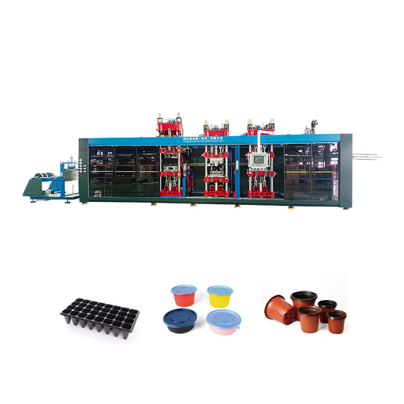
Tooling maintenance only pays off if the machine delivering heat and vacuum to that tooling is itself performing consistently. Three subsystems deserve regular attention beyond the mould.
Individually zoned heaters drift out of calibration at different rates. A thermal profile check across the heating platen, done quarterly at minimum, catches zones that have degraded before they translate into uneven sheet sag and localized thin-walling.
Vacuum draw speed directly affects detail replication, especially in deep-draw parts. A pump losing efficiency due to worn seals or oil degradation often shows up first as slower cycle times before it becomes a visible quality issue, which makes cycle time trending a useful early warning tool.
An out-of-square clamp frame places uneven tension on the sheet during forming, and that uneven tension transfers directly into the mould as asymmetric wall thickness. Frame alignment should be checked whenever a mould change reveals inconsistent trim margins on opposite sides of a part.
When a defect appears, the fastest diagnostic path is to separate mould-side causes from auxiliary and extruder-side causes before making adjustments. The table below organizes common symptoms by likely origin.
| Symptom | Likely Origin | First Check |
|---|---|---|
| Trapped air bubbles | Mould tooling | Vent hole clogging or undersized venting |
| Uneven wall thickness, one side | Auxiliary or machine | Feed roller tension, clamp frame alignment |
| Gel specks or dark streaks | Extruder auxiliary | Regrind contamination, screen condition |
| Poor surface gloss | Mould tooling | Surface abrasion, polish loss |
| Slower cycle times | Machine | Vacuum pump efficiency, heater output |
| Ragged trim edges | Auxiliary | Trim blade sharpness |
The following cycle summarizes how the individual checks described above fit into a repeatable rhythm. Rather than treating inspection, cleaning, lubrication, and calibration as separate isolated tasks, plants that extend mould life the most treat them as one continuous loop with documentation feeding back into the next inspection.
Different pieces of equipment in a thermoforming line wear at different rates and respond to different types of attention. The comparison below is a general reference point; actual intervals should be adjusted based on run hours, resin type, and observed wear rate rather than followed rigidly.
| Equipment | Lightest Duty Interval | Heavy Duty Interval | Primary Risk if Skipped |
|---|---|---|---|
| Mould tooling | Monthly | Weekly | Surface defects, vent clogging |
| Auxiliary trim and feed | Monthly | Weekly | Edge quality, tracking drift |
| Extruder auxiliary/crusher | Monthly | Biweekly | Regrind contamination |
| Vacuum pump | Quarterly | Monthly | Slower cycles, poor detail |
| Heater zones | Quarterly | Monthly | Uneven sag, thin-walling |
As a general guideline, lines running abrasive or filled resins, or operating close to continuous three-shift schedules, should default toward the heavy duty column even if current defect rates look acceptable. Wear accumulates well before it becomes visible in finished parts, and by the time a defect trend appears, the underlying tooling condition is often already several intervals behind.
Full disassembly is generally reserved for quarterly deep maintenance unless production data shows earlier signs of vent clogging or cooling channel scaling. Routine surface cleaning and vent checks should still happen weekly without full disassembly.
Uneven wall thickness most often traces back to sheet feed tension or clamp frame alignment rather than the mould cavity itself. Checking auxiliary feed systems before adjusting the mould saves significant troubleshooting time.
Higher regrind ratios concentrate contamination and can introduce inconsistent melt flow, which forces the mould to compensate through longer dwell times or deeper vacuum draw. This added stress accelerates surface wear over time even though the mould itself is not the source of the problem.
Small hairline cracks caught early can often be addressed through localized welding and refinishing. Once cracking propagates near cooling channels or thin structural ribs, insert replacement becomes the more reliable long term option.
A gradual increase in cycle time is usually the earliest measurable indicator, often appearing before any visible part quality issue. Tracking cycle time trends over weeks, rather than relying on visual inspection alone, catches this drift earlier.
They should be scheduled on a shared calendar rather than independently, since issues on one side frequently masquerade as defects on the other. Coordinated scheduling also reduces total line downtime by consolidating stoppages into fewer, longer maintenance windows.

 +8618621972598
  +8613917961988
  [email protected]
 No. 565, Xinchuan Road, Xinta Community, Lili Town, Wujiang District, Suzhou City, China
 Copyright © 2024 Thermoforming Machine/Plastic Cup Machine All Rights Reserved.Custom Automatic Vacuum Thermoforming Plastic Machine Manufacturers



 English
 عربى
عربى 简体中文
简体中文